

Resistance Temperature Detectors (RTDs) play a crucial role in industrial temperature measurement, especially in process and oil & gas applications. However, choosing the right wiring configuration can make the difference between accurate readings and costly measurement errors.
Understanding how 2-wire, 3-wire, and 4-wire RTD configurations work helps engineers select the optimal solution for their specific application requirements.
RTD sensors measure temperature by detecting changes in electrical resistance as temperature varies. The challenge lies in distinguishing between resistance changes caused by temperature and those caused by lead wire resistance. Each wiring configuration addresses this challenge differently, impacting overall measurement precision.
Lead wire resistance becomes particularly problematic in industrial settings where sensors must be positioned far from control instruments. Even small resistance values in copper extension wires can translate to significant temperature measurement errors.
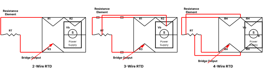
The 2-wire setup represents the most basic RTD connection method. This configuration connects one lead wire to each end of the RTD sensing element, creating the simplest possible circuit design.
In a 2-wire system, the measurement device reads the total resistance, which includes both the RTD element resistance and the resistance of both connecting wires. This means the displayed temperature reading will always be artificially elevated because the system cannot differentiate between sensor resistance and lead wire resistance.
The 3-wire configuration adds a third conductor to help compensate for lead wire resistance effects. This design has become the most widely adopted solution in industrial temperature measurement applications.
Three-wire systems connect two leads to one end of the RTD element and a single lead to the other end. The measurement instrument uses the third wire to determine lead wire resistance and mathematically removes this value from the total resistance reading. This compensation method assumes all three lead wires have identical resistance values.
Four-wire RTDs represent the most accurate temperature measurement configuration available. This design completely eliminates lead wire resistance effects from temperature measurements.
The 4-wire configuration uses separate wire pairs for excitation and measurement functions. Two wires carry the measurement current to energize the RTD element, while the other two wires sense the voltage developed across the sensor without carrying any current. Since the voltage-sensing wires carry no current, their resistance values do not affect the measurement.
Choosing between configurations depends on several key factors:
Use identical wire specifications for all conductors in 3-wire and 4-wire systems. Route cables away from power conductors and electromagnetic interference sources. Proper cable shielding and grounding help maintain signal integrity.
High-quality terminal connections ensure reliable long-term operation. Use appropriate connector types rated for the operating environment and temperature range. Regular inspection helps prevent degradation.
Establish proper calibration procedures appropriate for the selected configuration. Document baseline performance and implement periodic verification to ensure continued accuracy.
While 2-wire systems offer cost advantages for simple monitoring, 3-wire configurations provide the accuracy improvements needed for most industrial process control. Four-wire systems deliver maximum precision for laboratory and critical control environments where measurement accuracy directly impacts results.

 Singapore