Practical Selection Guide and Layout Techniques for TVS Diodes
Practical Selection Guide and Layout Techniques for TVS Diodes
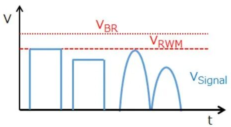
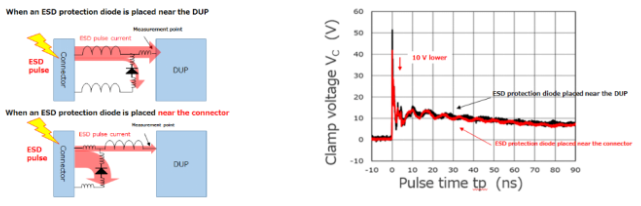
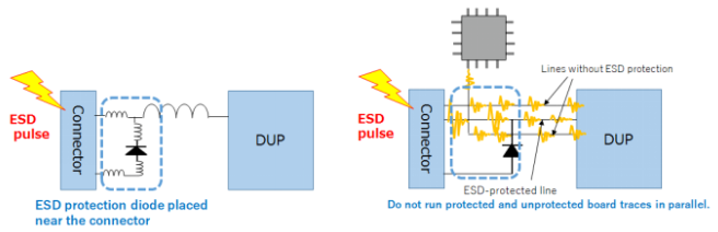
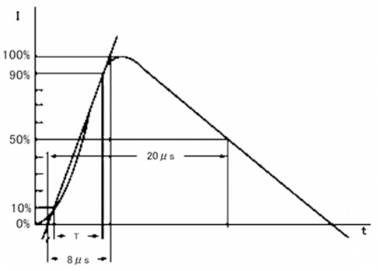
In the first three lessons, we delved into the working principles, types, and selection considerations of TVS diodes. Today, let's master the practical selection guide and layout techniques for TVS diodes, bringing this series to a perfect close. Selection Guide: Choosing the Most Suitable "Guardian" for Your Circuit Choosing a TVS diode is like selecting a bodyguard for your circuit, requiring consideration of three key dimensions: First, ensuring signal quality. We need to select a TVS diode with an appropriate reverse breakdown voltage (VBR) based on the maximum voltage of the protected signal line. This value should be higher than the normal operating voltage of the signal, but not so high that it loses its protective function. For analog signals crossing GND levels, a bidirectional TVS diode should be selected; while for high-speed signal lines, special attention should be paid to the total capacitance (CT) parameter to ensure that it does not affect signal transmission quality. Second, improving ESD protection performance. Dynamic resistance (RDYN) is an important indicator of TVS diode performance; the lower the dynamic resistance, the better the protection effect. Simultaneously, the clamping voltage (VC) must be lower than the withstand voltage of the protected device to ensure the safety of downstream devices during surge events. Finally, ESD withstand capability needs to be verified. We need to select TVS diodes conforming to the IEC 61000-4-2 standard to address ESD threats, and products conforming to the IEC 61000-4-5 standard to withstand larger surge impacts. It is important to note that protection performance is usually directly proportional to total capacitance, requiring a reasonable trade-off between protection strength and signal integrity. Figure 1. Maximum Reverse Voltage (VRMW), Reverse Breakdown Voltage (VBR) and Signal Line Voltage (VSignal) Layout Considerations: The Golden Rule for Maximizing Protection Effectiveness Excellent TVS diodes require a proper layout to achieve maximum effectiveness: Location is key: TVS diodes should be placed as close as possible to potential ESD entry points (such as connectors) to intercept threats at the first instance. Figure 2. Clamping voltage difference depends on the location of the TVS diode. Keep the path simple: The trace from the connector to the TVS diode and its ground point should be as short and straight as possible to minimize parasitic inductance and ensure that surge current is quickly discharged to ground. Isolate the wiring: Avoid running other sensitive signal lines parallel to signal lines that may introduce ESD pulses, especially for devices with weak ESD immunity, to prevent secondary damage caused by coupling interference. Figure 3. TVS diode circuit board traces Terminology Explanation: Essential knowledge for understanding datasheets To better select and use TVS diodes, we need to understand several key terms: Absolute Maximum Ratings: The limiting parameters that a TVS diode can withstand, including maximum current, voltage, and power dissipation. These values should never be exceeded under any circumstances, otherwise permanent damage to the device may occur. ESD Withstand Voltage (VESD): Refers to the contact discharge ESD tolerance, which is divided into contact discharge and air discharge. The former is achieved through direct contact discharge with the protected device. ESD tolerance is tested according to the IEC 61000-4-2 standard; a higher value indicates stronger protection. Peak Pulse Power (PPK) and Peak Pulse Current (IPP): These represent the maximum surge power that the TVS diode can shunt before it fails, and the peak pulse current that it can shunt before it fails, respectively. The maximum surge energy that a TVS diode can handle is measured using a standard 8/20μs test waveform. Figure 4. TVS Diode Pulse Waveform Junction Temperature (Tj) and Storage Temperature (Tstg): These define the highest junction temperature at which a TVS diode can operate without degradation or self-damage, and the ambient temperature range within which it can be stored and transported without applied voltage. They are crucial parameters for ensuring reliability. Through this series of lessons, you should now have a comprehensive understanding of the TVS diode, this "circuit bodyguard." From basic principles to practical selection, from parameter understanding to layout techniques, we hope this knowledge will help you make wiser choices in future circuit designs!