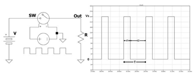
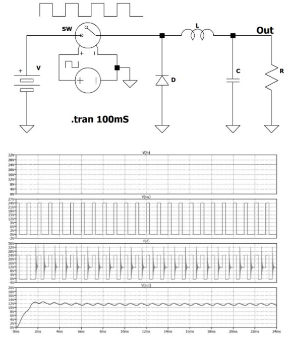
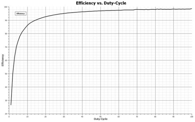
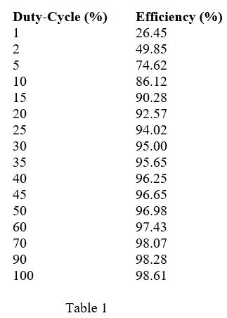
The necessity of converting one DC voltage to another is often central to numerous applications in industrial, medical, and even domestic fields. A more or less complex device, called a DC-DC converter, performs the change of DC voltage from one level to another. The voltage may change in an ascending or descending manner. In this chapter, we will examine the most commonly used methods. Changing the Voltage of a DC Power Supply – DC-DC Converters One of the main reasons for distributing electricity in the home in AC form is the simplicity of conversion. Transformers are sufficient to easily and safely raise or lower AC power supply voltages. Unfortunately, things are not so simple with DC voltage. Its conversion is much more complex, requiring special strategies, methods, and extremely sophisticated electronics. Converting DC voltage to another DC voltage is useful in a variety of electrical applications, such as the control of electric vehicle motors and all other applications that require continuous changes in rotational speed while maintaining torque and force parameters intact. With a DC-DC converter, it is easy to have a complex power supply that may operate using different power supply voltages as needed. Buck Converter (Step-Down) In a DC-DC switching circuit, energy is converted by storing energy using appropriately driven electronic switches and components. A buck converter, also known as a step-down converter, is a DC-DC power converter that reduces the input voltage and provides a lower output voltage. Modern technology today encapsulates the entire complex circuit structure in a single package. Theoretically, the input voltage could be reduced by using high-power resistors or power dividers, but the energy wasted unnecessarily in heat would be enormous, and such a solution would only return a few percentage points of efficiency. The basis of a switching circuit is an electronic switch (BJT, MOSFET, or others) that alternately turns on and off at a very high frequency (see Figure 1). The switching signal allows you to select the output voltage by simply changing its duty cycle. Figure 1: The switching signal allows you to select the output voltage by simply changing its duty cycle. If the SW switch is closed for time t1, there is a voltage Vs across the load R. Conversely, if the switch is open for time t2, the voltage across the load R is 0 V. The rapid succession of these pulses results in a voltage at the load between 0 V and Vs. The latter varies between 0% and 100% (PWM) as a function of the duty cycle. If the signal is generated by a rectangular or square wave, this voltage equals: In all other cases, the voltage equals: Buck DC-DC Converter with Resistor and Inductor as Load v(in): The DC input voltage, powering the entire conversion circuit; v(sw): The rectangular signal (pulse train) provided by the electronically switched system; v(d): The signal across the diode. It can be seen that it is affected by peaks and oscillations, causing the signal to saturate due to interference (EMI); v(out): The output signal is lower than the input signal. It may be affected by oscillations, which are intentionally amplified in the diagram. Typically, using a large output capacitor can significantly reduce this problem. Figure 2: Buck Converter with Resistor and Inductor as Load Now we can observe the operation and function of the electronic components in two different phases of DC-DC converter operation (i.e., when the switch is in the ON and OFF positions): When the switch is closed, current normally flows through it but not through the diode because the diodes have opposite polarities. Therefore, the capacitor is charged by this current. That is, the switch is in the normal on state, and current flows normally from the voltage generator to the load; Once the switch is open, the inductor reverses the voltage across its terminals and turns the diode on. This component also suppresses any surges that may occur when the switch is open. In other words, the switch is not conducting, and the load current flows through the loop diode. The average current in the inductor is approximately equal to the output current. In the “ON” phase, the current in the MOSFET will equal the average current in the inductor plus the ripple. Conversely, in the “OFF” phase, the current flowing through the diode equals the average current in the inductor plus the current ripple. If the inductor and capacitor are ideal, the efficiency of this circuit will be 100%. In fact, this ratio is approximately 94%. The efficiency of the circuit largely depends on the duty cycle of the PWM signal. In particular, when the output voltage is much lower than the input voltage, a large current is built up at the switch, leading to unnecessary energy waste. As can be seen from Figure 3, the efficiency of the DC-DC converter is also low when the duty cycle is low. Therefore, converters with a duty cycle below 20% should be avoided to achieve a high reduction ratio. Note that both ratios shown in the figure are expressed as percentages. The efficiency of a buck converter largely depends on the PWM duty cycle, i.e., the reduction ratio of the output voltage under the same load. Figure 3: The efficiency of a buck converter largely depends on the PWM duty cycle, i.e., the reduction ratio of the output voltage under the same load. The table below shows some duty cycle values for the switches and the corresponding system efficiency values. Of course, this is general data and may vary slightly depending on many circuit parameters. This type of DC-DC converter processes signals that are not very clean, as shown in the spectrum diagram in Figure 4, where multiple harmonics are present in the signal. The first spectrum above shows the harmonics present in the diode, while the second spectrum shows the harmonics present after the inductor. Therefore, designers should implement a good filter system to eliminate or reduce these types of unwanted signals as much as possible.