What is DC IR Drop? What is the significance of DC IR Drop simulation?
What is DC IR Drop? What is the significance of DC IR Drop simulation?
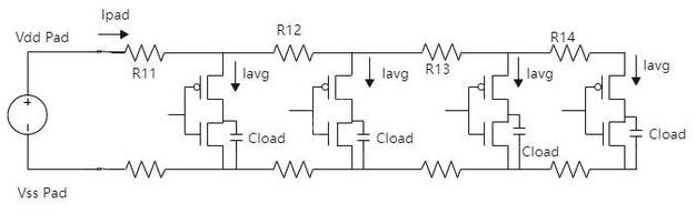
I. What is DC IR Drop? DC stands for Direct Current, where the direction of current does not change over time. In IR Drop, I refers to current, and R refers to resistance. The product of I and R is the voltage, and IR Drop is the voltage drop. A power distribution system, composed of power and ground traces, planes, and decoupling capacitors, has parasitic parameters such as resistance, inductance, and capacitance, resulting in a non-zero impedance. When the chip's operating current is output from the power supply, flows through the power distribution network to the chip, it creates a DC voltage drop at the chip. With the continuous evolution of semiconductor technology, the supply voltage of integrated circuits (ICs) continues to decrease, while the operating current of devices continues to increase. The width of metal interconnects is becoming narrower, while R = ρL/S (where ρ represents the resistivity of the conductor material, determined by its inherent properties, L represents the length of the conductor, and S represents the cross-sectional area of the conductor), the resistance value is constantly increasing, and the IR drop effect becomes more and more obvious. This problem makes it impossible for the power supply to provide sufficient voltage to the integrated circuit, which may lead to instability in the integrated circuit's operation. II. IR Drop Classification Static IR Drop Static IR drop is mainly caused by voltage division in the metal interconnects of the power supply network. Current flowing through these internal power supply interconnects generates a voltage drop. The static voltage drop calculation does not consider current changes over time, or rather, it uses the average current over a long period to represent the load current. Resistance calculation is also relatively simple, as it doesn't heavily consider the skin effect on resistance; the resistance value can be extracted from the power supply network and assumed to be constant. Static IR drop is mainly related to the structure and interconnection details of the power supply network; therefore, the analysis primarily considers the resistance effect. Dynamic IR Drop Dynamic IR drop is the voltage drop caused by current fluctuations during circuit switching. This phenomenon occurs at the clock edge. The clock edge transition not only triggers a large number of transistor switching but also causes transitions in combinational logic circuits, often generating a large current across the entire chip in a short period. This instantaneous large current causes IR drop. The more transistors switching, the more likely dynamic IR drop is to be triggered. IR drop can be local or global. When a certain number of logic gates in adjacent locations simultaneously perform logic toggles, a local IR drop occurs. Similarly, a particularly high resistance in a specific part of the power grid (e.g., R14 in the diagram below is significantly higher than expected) can also cause a local IR drop. When logic operations in one region of the chip cause IR drop in other regions, this is called a global IR drop. Equivalent power network diagram III. What are the dangers of IR drop? IR drop often manifests as timing or even signal integrity issues. If the global IR drop of a chip is too high, logic gates will malfunction, causing the chip to fail completely, even if logic simulation shows the design is correct. Local IR drop is more sensitive; it only occurs under specific conditions, such as when all bus data toggles synchronously, thus causing the chip to intermittently exhibit functional failures. A common impact of IR drop is reduced chip speed. Experiments show that a 5% IR drop on a logic gate will reduce normal gate speed by 15%. If the IR drop occurs on a timing-critical path, the consequences will be even more severe. IR drop also poses potential thermal hazards: during routing, the power plane can be disrupted by drilling into other layers, causing the once-intact power plane to become fragmented. Highly integrated ICs are often placed above this area; when large currents flow through it, the high resistance causes the temperature in this area to rise, affecting the overall IC heat dissipation. This can lead to performance degradation (increased thermal noise), and in the worst case, system crashes. IV. Why Perform DC IR Drop Simulation? With advancements in semiconductor technology, the high-current, low-voltage design of large-scale integrated circuits increases DC voltage drop, reduces AC noise margin, and increases the difficulty of power integrity (PI) design; simultaneously, electromigration caused by current density can cause reliability issues. Therefore, DC IR drop analysis is necessary (although PI problems are transient, DC analysis of the power supply is the first step). For DC analysis, appropriate voltage and current sources need to be placed to visually observe the current flow and voltage drop from the results. The simulation can be completed step-by-step according to the simulation flowchart. The key to simulation lies in understanding the circuit loop and the rationality of the placed voltage and current sources. The selection of decoupling capacitors requires calculation based on the resonant frequency to choose an effective filtering value. All power supply chips have a nominal output voltage and voltage fluctuation range under their respective designs, and each discrete component also has a nominal normal operating voltage and upper/lower tolerance range. These given conditions, combined with simulation results, are needed to determine whether the power distribution system design meets the requirements. Internal IR drop issues within the chip can be analyzed using simulation methods. Currently, the mainstream approaches include static analysis and dynamic analysis. Static analysis generally only considers parasitic resistance; dynamic analysis also considers the effects of parasitic capacitance and inductance. Currently, for designs of 130nm and above, static IR drop analysis is still widely used, effectively analyzing IR drop caused by open power rails, lost vias, insufficient power straps, insufficient power line width, etc. Back-end design can use static IR drop analysis to first optimize the IR drop to within 2%-5% (the specific value depends on the actual project), and then use dynamic analysis to analyze transient IR drop. Conclusion DC IR Drop is directly related to interconnect impedance and power supply current. Conventionally, a 1mm trace width corresponds to 1A of current, which meets power supply current requirements. However, with multiple power supplies, bottleneck areas on the board can be difficult to identify. Power supply simulation is needed to identify bottlenecks and areas where requirements are not met. IR Drop simulation reveals areas of high and low voltage drop in the power supply design and can also determine if excessive current density is causing copper overheating.