How to get more power by paralleling silicon carbide MOSFETs?
How to get more power by paralleling silicon carbide MOSFETs?
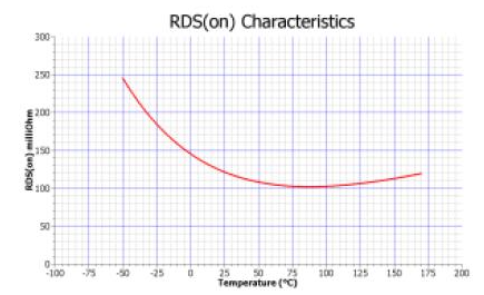
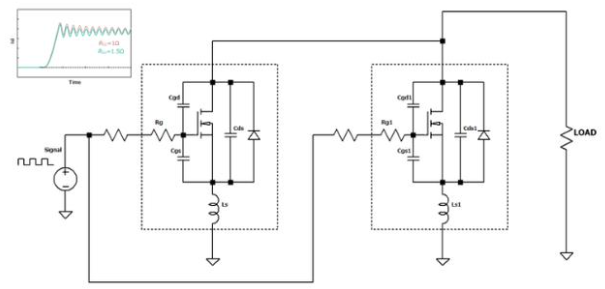
To divide the power involved and create devices that can handle more power, switches, resistors, and MOSFETs are connected in parallel. To increase the output current capacity, you can connect them in parallel. Parallel connections are generally easier and less critical compared to other older components because they are not affected by thermal instability. Furthermore, SiC MOSFETs can be connected and operated in parallel with other similar devices. In typical cases, direct connections between many parallel units can work efficiently, but operating conditions can deteriorate under extreme conditions involving temperature, current, and operating frequency. Therefore, to fully utilize the benefits of paralleling power devices, careful consideration must be given to building fault-tolerant circuitry. Some Considerations Parallelizing power devices is feasible when they have the same electrical characteristics and the same static and dynamic behavior. However, this is not always possible in reality due to the inherent differences between numerous samples. MOSFETs are used as electronic switches to achieve “slow” switching in selected applications where they operate in a static state. However, most applications involve rapid, continuous switching. Even within the same type of MOSFET, minute (even imperceptible) variations in its electrical characteristics can cause transient voltage spikes and an overall imbalance in current distribution. This problem can lead to significant power loss, noticeable circuit heating, and electronic component failure. Designers must study the circuit to ensure that the current carried is well-balanced and uniform across all power devices of similar characteristics under all operating conditions. When switching devices, it is advisable to avoid current concentration on certain electronic components. In fact, this can lead to unwanted oscillations and imbalances in electronic switching operation. Common problems and causes of non-ideal parallel connections include: Mismatched device parameters; On-resistance mismatch (RDS(on)); Gate-source voltage mismatch (VGS); Gate driver mismatch; Power supply circuit mismatch. On-resistance: On-resistance RDS(on) is one of the fundamental parameters of a MOSFET. It affects many operating factors, such as component dissipation, maximum current carried, system efficiency, and conduction losses. When the MOSFET is off, the drain-source voltage is high, and no current flows. On the other hand, when it is active, the drain-source voltage drops to several hundred millivolts. The RDS(on) parameter of SiC MOSFETs is highly temperature-sensitive, so care must be taken when designing circuits with parallel devices (see the graph in Figure 1). Their internal conformation determines both negative and positive temperature coefficients, which can lead to current imbalances. The graph confirms that the channel resistance changes according to the junction temperature of the SiC MOSFET. Simple parallelization of many device examples can cause problems because one component may carry more current than another. Therefore, it is necessary to dissipate the heat of all MOSFETs equally. Figure 1: RDS(on) vs. Junction Temperature Various Imbalances When the MOSFET is open, a small current flows in parallel through the electronic switch, inversely proportional to its activation resistance. Obviously, the device with the lowest resistance carries more current. Fortunately, SiC MOSFETs are characterized by positive temperature compensation, so a more natural balance occurs in the circuit, minimizing thermal damage to the components. On the other hand, the diodes contained within MOSFETs behave differently; as current flows, the temperature rises by reducing the current being carried. Current imbalances can occur during switching, especially during power-on and power-off. Unnecessary Oscillations Oscillations are high-frequency signals that alter the normal operation of a device. In fact, the special conformation of a MOSFET constitutes a resonant circuit equipped with a capacitor (C) and an inductor (L). Both of these elements are clearly parasitic components. Without an external gate resistor, the resonant circuit would have a very high Q factor. If resonance occurs, a significant oscillating signal is generated between the "gate" and "source" terminals, producing parasitic and unwanted oscillations, corresponding to equal oscillations between the "drain" and "source" terminals. Excessively high oscillation voltages can lead to misfires or MOSFET malfunctions. However, in general, paralleling SiC MOSFETs does not involve a high risk of oscillations, so with necessary precautions, the circuit can operate without problems. Solutions Today, many companies produce SiC power modules by paralleling multiple MOSFETs, and of course, some precautions are taken. Some manufacturers obtain very powerful components because this type of connection increases power dissipation, and most importantly, reduces the RDS (turn-on) parameter, just as occurs in a resistor parallel connection. Typically, SiC MOSFETs can be paralleled without special measures because their internal resistance increases when they overheat, distributing the load fairly evenly despite inherent differences between the individual components. One significant drawback is the increased "gate" capacitance, leading to increased on-time of the SiC MOSFETs. In these cases, the gate current must be significantly increased, depending on the number of devices paralleled. At high frequencies, this can become unacceptable. For older power components such as IGBTs, designers must overcome ongoing challenges (balancing, excellent drivers, etc.) to establish good parallel connections between power devices. This challenge can be amplified when using SiC MOSFETs due to the much higher switching frequencies involved. The primary purpose of paralleling components is to achieve higher rated current. Designers also need to consider PCB layout. They should have a symmetrical structure to distribute generated heat and significantly reduce parasitic inductance. Therefore, these solutions provide the correct parallel connection of SiC MOSFETs to increase the current and power levels transmitted. However, some precautions need to be taken into account: Threshold voltage may cause current imbalance. Current imbalance may occur due to parasitic inductance asymmetry. Possible fluctuations. Nowadays, companies have achieved a high degree of manufacturing perfection, producing SiC MOSFET devices that are nearly identical to each other, and the possibility of imbalance is very small. However, devices with lower threshold voltages have higher transients, resulting in higher switching and conduction losses and higher overall power losses. Typically, if the current flowing through the load is greater than the nominal value of each device to be used, it is safe to connect two devices in parallel to halve the current flowing through each switch. Figure 2 shows a solution that allows for the use of an external gate resistor (for each MOSFET) to reduce switching variations between the various devices. Using an external gate resistor is not a miracle; imbalance may still occur. In some cases, VGS may also oscillate in this configuration due to an RLC resonant circuit between the two MOSFETs. Silicon carbide MOSFETs are characterized by a positive temperature coefficient. It acts as negative feedback when sharing quiescent current. If a device draws more current, it heats up, thus increasing its RDS (on-state). In this way, the current in the transmission is reduced, and the level of thermal imbalance is also reduced. Furthermore, they show that switching losses increase very little with increasing temperature. Finally, SiC MOSFETs exhibit a smoother transconductance profile, and small changes in gate voltage have a smaller impact on current, which is beneficial for dynamic current sharing among multiple devices.