Passive Crystal Oscillator Startup Conditions and Operating Principles
Passive Crystal Oscillator Startup Conditions and Operating Principles
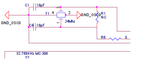
A passive crystal oscillator (crystal), also known as a quartz crystal resonator, is essentially a quartz crystal unit. Crystal oscillator refers to both quartz crystal units and crystal oscillators. Microcontroller clock sources can be divided into two categories: those based on mechanical resonant devices, such as crystal oscillators and ceramic resonant tank circuits, and RC (resistance-capacitance) oscillators. One type is the Pierce oscillator configuration, suitable for crystal oscillators and ceramic resonant tank circuits. The other type is a simple discrete RC oscillator. Oscillators based on crystal oscillators and ceramic resonant tank circuits typically offer very high initial accuracy and a low temperature coefficient. RC oscillators also offer fast startup and are relatively low cost. Passive Crystal Oscillator Startup Conditions 1. No oscillation. The crystal oscillator may not operate after a power-on reset or in low-power mode, but it will start normally after a tap. This is a crystal oscillator underdrive, caused by insufficient drive power or a long start-up time. The solution is to select a crystal with low power consumption and reduce the external capacitance within the datasheet's permitted range to shorten the start-up time. The capacitance values should be different. 2. If the frequency is too high, this is an overdrive phenomenon. An oscilloscope can show flattened peaks and valleys in the output waveform. In this case, the crystal oscillator is overdriven. Resistors should be connected in series with the relevant pins on the chip to adjust the output waveform until the waveform is clear and complete. Operating Principle of Passive Crystal Oscillators First, crystal oscillators are a general term for both passive and active crystal oscillators. As we learned above, only passive crystal oscillators require matching capacitors; they are also called crystals. A crystal with a capacitance between 0.1µU and 0.01µU is considered relatively large. The nominal value of a crystal oscillator is tested with a "load capacitance" condition. Only when this condition is met during operation will the oscillation frequency match the nominal value. Generally speaking, there are low load capacitance (series resonant crystals) and high load capacitance (parallel resonant crystals). The circuit characteristics are as follows: A crystal oscillator with a capacitor connected across two pins of the IC is a series resonant type; one pin connected to the IC and one to ground is a parallel type. If the original model is unavailable and a replacement is needed, a capacitor in series with the capacitor in the series resonant circuit can be added, and a capacitor in series with the parallel resonant circuit can be added. For example, a 4.433MHz crystal oscillator can be connected with a 3300pF capacitor or a 70pF trimmer capacitor. Another way of saying this is "loss" value and "drive level": In fact, all of the above factors can be considered when selecting a crystal oscillator. Common crystal oscillators have two or four pins. There's actually little difference between two- and four-pin passive crystal oscillators, as they primarily rely on two pins for operation. A three-pin crystal oscillator is a composite component combining a crystal oscillator and a capacitor. Since the peripheral circuits of integrated circuit oscillator terminals often consist of a crystal oscillator (or other resonant element) and two capacitors, this composite component was developed to simplify the circuit and process. Of its three pins, the middle one is usually the common terminal where the two capacitors are connected together, and the other two pins are the two ends of the crystal oscillator, which are also the two ends of the two capacitors connected to the crystal oscillator. The working principle of a passive crystal oscillator (crystal resonator) is as follows: electrodes are plated on both sides of a quartz crystal sheet. When a certain voltage is applied to the two electrodes, the piezoelectric effect of the quartz causes the voltage to naturally deform, thereby providing a sinusoidal waveform to the IC. After internal shaping and PLL circuitry within the IC, this square wave is generated and then input to the downstream circuit. An active crystal oscillator integrates the frequency component and the PLL driver circuit external to the IC, forming a self-contained unit that directly outputs a square wave for use by downstream circuits.