Capacitors and Capacitors vs. Inductors and Inductors
Capacitors and Capacitors vs. Inductors and Inductors
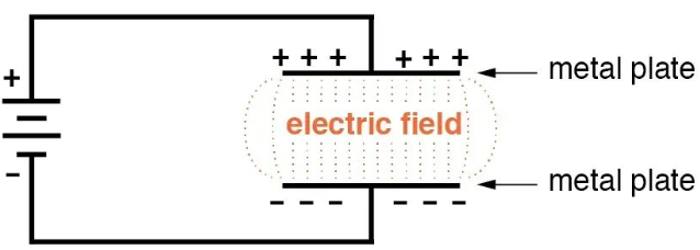
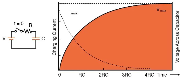
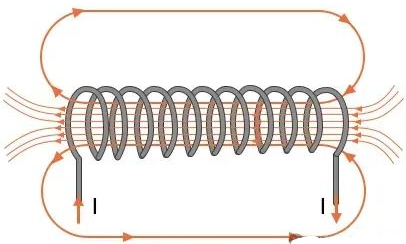
We've learned that voltage and current sources provide energy, enabling circuits to perform their intended functions. However, circuits are not simply composed of energy sources and energy-consuming components. In fact, two common electronic components—capacitors and inductors—are inherently capable of storing energy. These components serve as temporary energy sources and are widely used in power networks, voltage regulation circuits, and frequency-dependent circuits known as filters. Capacitors and Capacitors Capacitance exists whenever conductive materials are separated by insulating materials. A capacitor structure has the ability to store energy in the form of an electric field; when a capacitor structure is designed as an electrical element with a specific capacitance value, it is called a capacitor. We use the terms "charging" and "discharging" to identify the states of a capacitor gaining energy and discharging energy, respectively. As shown in the diagram, we can charge a capacitor by connecting it to a battery. Voltage causes current to flow, and this current transfers charge to the capacitor. The accumulation of charge creates a voltage across the capacitor, and as the current in the circuit gradually decreases, the voltage across the capacitor gradually increases. If a fully charged capacitor is disconnected from a battery and connected to a resistor, it will function as a voltage source because the energy stored in the electric field can convert the accumulated charge into moving charge—in other words, current. The voltage and current behavior associated with a charging capacitor is represented by the curves in the following graph. Note that the time axis uses the abbreviation "RC"; this refers to the RC time constant, which is the time period obtained by multiplying the capacitance (C) of the capacitor by the resistance in series with the capacitor. The capacitance of a component is a critical parameter in circuit design because, as the graph shows, it affects the rate of change of voltage (or current) during charging and discharging. The higher the capacitance, the slower the voltage across the capacitor increases (when it is charging) and the slower it decreases (when it is discharging). Quantifying Capacitance When electrical engineers incorporate capacitors into circuit diagrams, they must choose a capacitor with an appropriate capacitance value. A capacitor with a higher capacitance value can store more charge at a given voltage. We use farads as the unit to quantify capacitance, which corresponds to coulombs per volt. If a 2 microfarad capacitor and a 20 microfarad capacitor are both charged to the same voltage, the 20 microfarad capacitor will store ten times the charge of the 2 microfarad capacitor. Inductors and Inductance If you're comfortable with the basic concept of capacitance, you already have a good understanding of inductance, as the two phenomena are very similar—they can be described as "equal but opposite": A capacitor stores energy in an electric field; an inductor stores energy in a magnetic field. When a capacitor is connected to a voltage source, its voltage gradually increases while its current gradually decreases; when an inductor is connected to a voltage source, its current gradually increases while its voltage gradually decreases. For capacitors, the rate of charging and discharging is controlled by the RC time constant; for inductors, we use the RL time constant, which is the inductance (L) multiplied by the resistance connected in series with the inductor. If a capacitor circuit is disconnected from the power source, the capacitor will temporarily hold the voltage. If an inductor circuit is disconnected from the power source, the inductor will temporarily hold the current. In other words, capacitors "resist" changes in voltage, while inductors "resist" changes in current. All conductors, such as wires and component leads, have inductance. To create an inductor, we use techniques to strengthen the magnetic field, thereby increasing the inductance. A basic inductor is simply a coil; the following diagram illustrates how this structure concentrates magnetic field lines. Quantifying Inductance Inductance represents the amount of voltage produced in an inductor due to changes in the rate of charge flow. It is measured using a unit called the henry.